Share
Pin
Tweet
Send
Share
Send
In the same place, among the unnecessary junk, I also found a voltage regulator from an old TV, which in my opinion is wonderfully suitable as a case.

Having studied the vast expanses of the Internet and really appreciated his strength, he probably chose the simplest scheme.

Having printed the circuit, I went to a neighbor who is fond of radio electronics. Within 15 minutes he typed in the necessary details for me, cut off a piece of foil PCB and gave a marker for drawing boards. After spending about an hour, I drew an acceptable board (installation of a spacious case allows dimensions). I will not tell you how to poison the board, there is a lot of information about this. I took my creation to a neighbor, and he poisoned it with me. In principle, you could buy a circuit board and do everything on it, but as they say to a gifted horse ....
Having drilled all the necessary holes and displayed the pin of transistors on the monitor screen, I took up the soldering iron and after about an hour I had a finished board.

You can buy a diode bridge on the market, the main thing is that it is designed for a current of at least 10 amperes. I found diodes D 242 their characteristics are quite suitable, and on a piece of PCB I soldered a diode bridge.

The thyristor must be installed on the radiator, since during operation it is noticeably heated.

Separately, I must say about the ammeter. He had to buy it in a store, where the seller consultant also picked up a shunt. I decided to modify the circuit a bit and add a switch so that it was possible to measure the voltage on the battery. Here, a shunt was also needed, but when measuring voltage, it is connected not in parallel, but in series. The calculation formula can be found on the Internet, I’ll add that the dissipation power of shunt resistors is of great importance. According to my calculations, it should have been 2.25 watts, but I had a 4-watt shunt heated up. I don’t know the reason, I don’t have enough experience in such matters, but having decided that basically I need the readings of an ammeter, not a voltmeter, I measured it. Moreover, in the voltmeter mode, the shunt noticeably heated for 30-40 seconds. So, having collected everything I needed and checked everything on a stool, I took up the case. Having completely disassembled the stabilizer, I took out all of its filling.

Having marked the front wall, I drilled holes for a variable resistor and a switch, then I drilled holes for an ammeter with a small diameter drill around the circumference. Sharp edges finished file.

Having broken his head a little over the location of the transformer and radiator with a thyristor, he stopped at this option.

I bought a couple more clips "crocodile" and all-charging is ready. The peculiarity of this circuit is that it works only under load, therefore, having assembled the device and not finding the voltage at the terminals with a voltmeter, do not rush to scold me. Just hang at least a car light on the conclusions, and you will be happy.

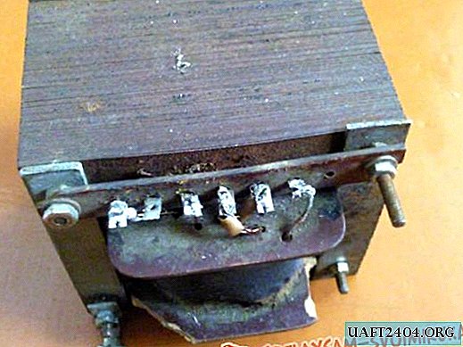
Take the transformer with a voltage on the secondary winding of 20-24 volts. Zener diode D 814. All other elements are indicated on the diagram.
Share
Pin
Tweet
Send
Share
Send

