Share
Pin
Tweet
Send
Share
Send

However, the price of these new relays, especially three-phase relays, makes you think about the appropriateness of their application. In this case, the independent manufacture of such a relay can help and this site will help you with this. Making a three-phase relay at 40 amperes with your own hands will cost you a maximum of 500 rubles, even if you buy all the parts, while the factory one costs several thousand. It’s worth considering. Right?
The factory relay, in case of damage to parts of the internal device, cannot be repaired and needs to be completely replaced. A home-made relay made by yourself will serve you for many years, because you will thoroughly know its device, and if any of its parts burn out, you will easily change them and continue to use this very useful device.
So let's get started.
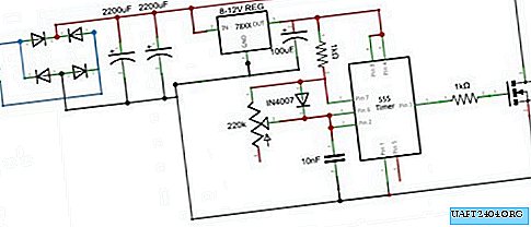
Solid State Relay Circuit

Details
For work we need.
- S1 - Any switch or toggle switch.
- F1 - fuse at 0.25 - 0.5 Amps.
- C1 - 0.068 uF 630 Volt.
- R1 - 470 kOhm.
- R2 - 100 Ohms.
- VDS1 - Rectifier bridge for 1 Ampere 600 - 1000 Volts or separate diodes.
- D1 - Zener diode at 20 Volts 0.5 watts.
- C2 - 10 μF 25 Volts.
- HL4 - any signal LED.
- MOC3063 - 3 pieces.
- R3, 7, 11 to 330 ohms 0.5 watts.
- C3, 5, 7 - each 2.7 nF 50 Volts. For current up to 10 amperes per phase. If you plan to load higher, then you need to put 3.3 nF.
- R4, 8, 12 to 470 ohms 2 watts. For current up to 10 amperes per phase. If you plan to load higher, then you need to put 330 ohms 2 watts.
- T1, 2, 3 - triacs BTA41-600 - 3 pieces.
- VD1, 2, 3, 4, 5, 6 - protective TVS diodes type 1.5 KE300CA.
- R5, 9, 13 - 47 ohms at 5 watts. For current up to 10 amperes per phase. If you plan to load higher, then you need to put 27 ohms 5 watts.
- C4, 6, 8 - at 0.047 uF 630 Volts. For current up to 10 amperes per phase. If you plan to load higher, then you need to put 0.1 μF 630 Volts.
- D2, 3, 4 - any diodes for a voltage of at least 600 volts. For example 1N4007.
- HL1, 2, 3 - any signal LEDs.
- R6, 10, 14 - 470 kOhm each.
- Development board - 2 pieces.
- Thermally conductive paste.

Solid State Relay Fabrication
It is best to start collecting parts from the case of the future device. Boxes for circuit breakers, which are sold in electrical goods stores, are well suited for this. The price is quite democratic and depends on the size of the box.
The most important detail of the future relay is a triac cooling radiator. The more comfortable the temperature for triacs during operation, the longer they will "live". In a word, the radiator should be as large as possible (within reasonable limits). If the case of the future relay is metallic, then the radiator plate can be tightly screwed to its rear wall, and then the whole case will be a large radiator.
BTA-41 triacs can be screwed without insulators directly to the radiator, since their terminals do not have electrical contact with the substrate. Other triacs must check the data.
Before mounting the circuit parts to the board, I tested the operation of the optocouplers, the photo shows how. Of the 20 pieces MOS3063-3 purchased in China, 3 were found to be defective. So be careful.


We begin the installation with the markup and installation in place of the triacs, and then the other parts.


We solder. Solder wires of increased diameter (depending on the load).


Very carefully remove the excess copper pads on the breadboard between the high-voltage wires (as in the photographs), in order to avoid short circuits. 380 Volts, this is a very high voltage and life-threatening.
We attach the following board with the findings of the parts.


We establish slots for optocouplers. If the optocoupler burns out in operation, then it can be replaced in a couple of seconds.


Install the control details.


We experience the operation of optocouplers.

Alternately, we supply 220 volts for each phase for verification.


We connect the device in turn to each phase and check the opening of the triac when the control voltage is turned on. 4.2 mOhm - the triac is closed.

The triac is open.

After making sure that the relay works, fill the places on the board where there is a high voltage with hot melt adhesive.


We lubricate the triacs with a heat-conducting paste and fix them on a radiator. The breadboard is mounted on insulating washers.


We fix the device in the case and close it. Three phase solid state relay ready for operation.

Test relay in operation, see the video.
Share
Pin
Tweet
Send
Share
Send